 |
IPSDK 4.2
IPSDK : Image Processing Software Development Kit
|
|
IPSDK 4.2
IPSDK : Image Processing Software Development Kit
|
| image = | addMarkerImg (inLabelImg,inBinImg,labelValue) |
Assign a new label value to the pixels determined by the input binary image.
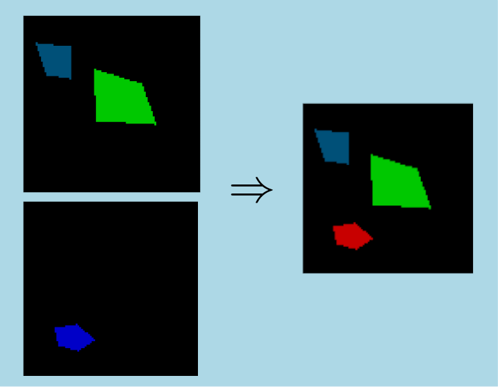
This algorithm allows to add a new connected component to the input label image. This new connected component is described by the pixels set to true in the input binary image. The value of the label is provided by the user with the third parameter.
The figure below illustrates an example with the input label (top left) and binary images (bottom left) and the output label image (right) :
| IPSDKIPLBASICMORPHOLOGY_API image::ImagePtr ipsdk::imaproc::morpho::addMarkerImg | ( | const image::ImageConstPtr & | pInLabelImg, |
| const image::ImageConstPtr & | pInBinImg, | ||
| const ipUInt32 | labelValue | ||
| ) |
wrapper function for Assign a new label value to the pixels determined by the input binary image
| ipsdk::processor::IPSDKBaseProcessingException | on failure |
| IPSDKIPLBASICMORPHOLOGY_API void ipsdk::imaproc::morpho::addMarkerImg | ( | const image::ImageConstPtr & | pInLabelImg, |
| const image::ImageConstPtr & | pInBinImg, | ||
| const ipUInt32 | labelValue, | ||
| const image::ImagePtr & | pOutLabelImg | ||
| ) |
wrapper function for Assign a new label value to the pixels determined by the input binary image
| ipsdk::processor::IPSDKBaseProcessingException | on failure |
 1.8.14
