 |
IPSDK 4.2
IPSDK : Image Processing Software Development Kit
|
|
IPSDK 4.2
IPSDK : Image Processing Software Development Kit
|
| image = | unrollCylinderImg (inImg3d,inOutputImgSizeX,center2d,radius,theta0,interpolationPolicy) |
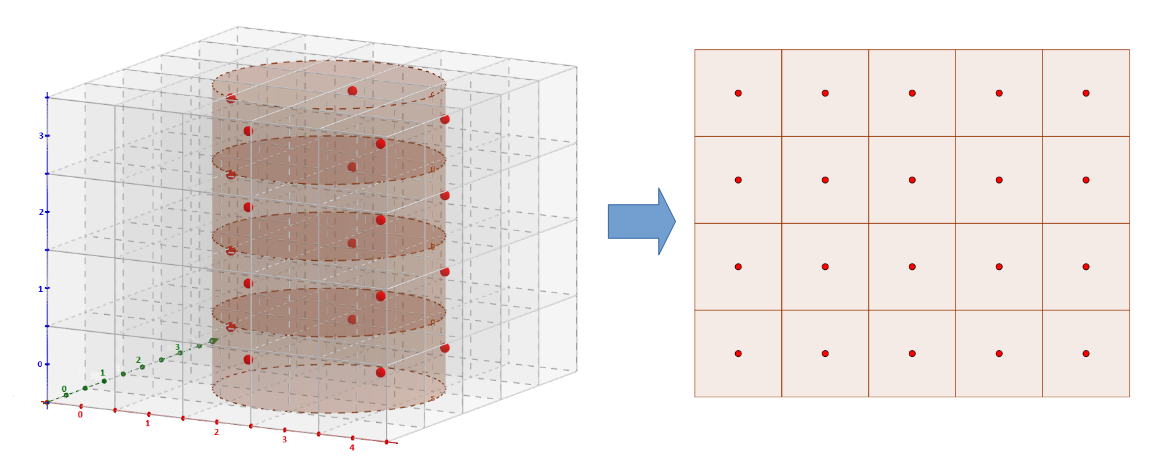
Unrolls into a 2D image a cylinder contained in a 3D image.
Considering:
 of dimensions
  ,
, ,
, attribute and z at
  (in other words, projection of cylinder center along z-axis coincides with center of image along z-axis, x and y coordinates are specified by the user), and a radius
  specified by the user,
 ,
, , in radians.
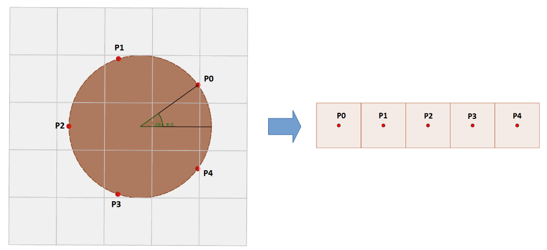
The UnrollCylinderImg algorithm computes the 2D array of interpolated intensities of voxels of input image along the surface of the cylinder. Each row of the resulting 2D array corresponds to a XY plan of the input 3D image. So the 2D array contains  rows, and each row contains
  values, that correspond to the intensities computed on regularly spaced samples along a circle (intersection between the cylinder and the current XY plan) of center and of radius . As the coordinates of these samples may be floating values, their intensities are computed interpolating their closest voxels in current XY plan. The user can choose between 3 types of interpolations (
  attribute): nearest neighbour, linear and cubic.
Values of the computed 2D array are finally returned in the 2D output image  .
.
The following figures illustrate how the pixels of the output 2D image are computed from the input 3D image and from the cylinder:
By default, the surface of the defined cylinder has no thickness, but optionnally, a non-null half-thickness can be specified. In that case, for each one of the  samples, the user can choose to get the mean, the minimum or the maximum of the
  sub-samples along the thickness of the surface.
Mathematically, values of the output images are defined as follows, depending on the thickness of the cylinder and on the retained integration type (mean, minimum or maximum):
![\[ OutImg2d(x, y) = InImg3d(radius \cdot cos(\theta_0 + \theta_x), radius \cdot sin(\theta_0 + \theta_x), y) \]](form_766.png)
an angle offset, in radians, specified by the user,
non-null thickness, mean:
![\[ OutImg2d(x, y) = \frac{\sum\nolimits_{\forall i \in [-halfThickness..halfThickness]}{InImg3d(radius \cdot cos(\theta_0 + \theta_x), radius \cdot sin(\theta_0 + \theta_x), y)}}{2 \times halfThickness + 1} \]](form_768.png)
non-null thickness, minimum:
![\[ OutImg2d(x, y) = \min\nolimits_{\forall i \in [-halfThickness..halfThickness]}{InImg3d(radius \cdot cos(\theta_0 + \theta_x), radius \cdot sin(\theta_0 + \theta_x), y)} \]](form_769.png)
non-null thickness, maximum:
![\[ OutImg2d(x, y) = \max\nolimits_{\forall i \in [-halfThickness..halfThickness]}{InImg3d(radius \cdot cos(\theta_0 + \theta_x), radius \cdot sin(\theta_0 + \theta_x), y)} \]](form_770.png)
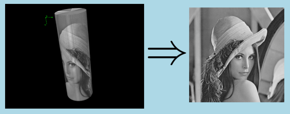
Here is an example of application of UnrollCylinderImg algorithm; the input image is a synthesis image generated by artificially rolling the 2D Lena image around a cylinder in an originally black 3D image; to make image reading easier on the snapshot below on the left, black pixels are masked, so that we can see the intensities of the cylinder surface; the result of algorithm application is displayed on the right: