 |
IPSDK 4.2
IPSDK : Image Processing Software Development Kit
|
|
IPSDK 4.2
IPSDK : Image Processing Software Development Kit
|
| HoughCircles2dPpties = | houghCircles2d (inImg,radiusRange) |
| HoughCircles2dPpties = | houghCircles2d (inImg,radiusRange,nbCircles) |
| HoughCircles2dPpties = | houghCircles2d (inImg,radiusRange,eCircleIntensityType,nbMaxPtsPerCircle,accumIntensityThreshold,removeTooCloseCirclesParams) |
| HoughCircles2dPpties = | houghCircles2d (inImg,radiusRange,eCircleIntensityType,nbCircles,nbMaxPtsPerCircle,accumIntensityThreshold,removeTooCloseCirclesParams) |
| HoughCircles2dPpties = | houghCircles2d (inGxImg,inGyImg,radiusRange) |
| HoughCircles2dPpties = | houghCircles2d (inGxImg,inGyImg,radiusRange,nbCircles) |
| HoughCircles2dPpties = | houghCircles2d (inGxImg,inGyImg,radiusRange,method,eCircleIntensityType,maxAngleWithGradDir,nbMaxPtsPerCircle,accumIntensityThreshold,removeTooCloseCirclesParams,outImg1,outImg2) |
| HoughCircles2dPpties = | houghCircles2d (inGxImg,inGyImg,radiusRange,method,eCircleIntensityType,nbCircles,maxAngleWithGradDir,nbMaxPtsPerCircle,accumIntensityThreshold,removeTooCloseCirclesParams,outImg1,outImg2) |
detects circles in image using Hough algorithm
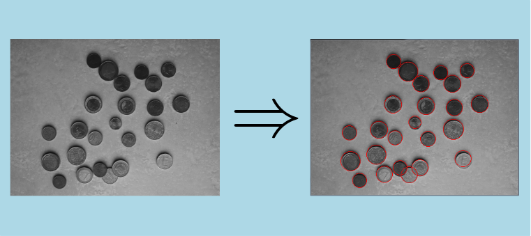
This algorithm uses a variant of the Standard Circle Hough Transform to detect circles in a 2d grey levels image (or in a sequence of 2d grey levels images). Below is shown an example of application of Hough circles detector on an image of coins (circles detected by the algorithm are drawn in red on the right image; used range of radii equals to [10, 20]; all other input parameters are left to their default values):
Standard Circle Hough Transform was inspired from Standard Line Hough Transform ([1]). Considering the user wants to detect circles with radii between minRadius and maxRadius, it works as follows:
a- pre-process the image by applying an edge extraction (Canny edge extraction, for instance)
b- create a 3D parameter space (also called accumulator matrix, or Hough space, or voting space). The 2 first dimensions correspond to the positions of the centers of the circles, and the 3rd dimension corresponds to the radii of the circles. Initialize the content of this 3D image with zeros.
c- for each pixel  of the edge(s) detected in the input image in a), and for each radius
  in
in ![$[minRadius;maxRadius]$](form_363.png) , increment pixels of coordinates
, increment pixels of coordinates  in the 3D parameter space that satisfy the equation
  .
.
d- extract local maxima in the 3D parameter space; they should correspond to the circles present in the original image
This algorithm has several limitations; in particular:
The current implementation makes use of modifications described in [2]. Here is a recall of the main modifications from the standard version:
The current implementation executes the following steps:
a- compute the gradient images if necessary, respectively along x and y axis
b- compute the Hough image (or images, if the "phase coded" method has been chosen)
c- extract the circles centers from the Hough image(s). The way to proceed depends on the selected method:
d- compute the radius associated to each detected circle:
e- for each couple of too close circles, remove the one with the lower accumulation intensity in Hough image
As a general rule, more the user will restrict the search parameters, the faster the algorithm will execute and the more accurate the result will be. Here are some details for each parameter:
 or the couple
  ): the user can choose between specifying directly the image in which he wants the circles to be detected (it has to be a grey-level 2d image, or a sequence of grey-level 2d images; if the user wants to detect circles in a color image, he can first convert it to a lightness image using ipsdk::imaproc::color::lightnessImg function, for instance) or entering the gradients images, respectively along the x and y axis. In the first case, the algorithm will first compute internally the gradient images, necessary for the next processing steps.
 ): specify the minimal and maximal radii of the set of circles to detect. Remember the general rule: the smaller the range will be, the faster the algorithm will execute and the more accurate the result will be.
 ): choose between "gradient" and "gradient phase-coded" methods. Default method is set to "gradient"
 ): 3 values are possible for this parameter:
 , expressed in radians): on clean (ie. without noise) images, a small tolerance (a few degrees) should be used, so that edge points with wrong gradient orientation do not take part to the vote in the Hough image. On the other hand, when the image is noisy, the user should increase the value of this parameter, because the gradient orientation is very sensitive to noise. Default value of this parameter is set to 5 degrees
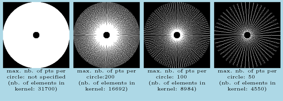
 ): this parameter determines the number of points per circle in the annulus kernel that will take part to the vote in the Hough image. The smaller this parameter is, the faster the computation is. Nevertheless, it is advised not to set this parameter to a too small value (< 50), especially on noisy images, or on images where circles are too close from each other, otherwise the accuracy of the results will be dramatically reduced. To determine the points for each circle in the kernel that take part to the vote, each circle is subsampled by keeping only one point every
  radians. Here are some examples of kernels associated to a range of radii [10; 100], with different values for parameter (pixels belonging to the kernel are colored in white, in a square window of size
  ):
):
 ): there are 2 thresholds for this parameter: an absolute one (default value: 1.0) and a relative one (default value: 0.3). Extraction of local maxima in the parameter space will only be applied on pixels whose value is greater than the absolute one AND greater than the relative one multiplied by the global maximum of the parameter space. Default values have been set to satisfy most of the use cases, but the user can adjust these 2 parameters if the number of circles detected in his input image is too low or too great.
minimum ratio of distances between two circles (  ): if this parameter is enabled, after the step of local maxima extraction in the parameter space, any circle
  , of parameters
  verifying the following condition:
  , a circle of parameters
  , so that:
< accumulation intensity of pixel in parameter space associated to  and is lower than
is removed from the collection of detected circles returned to the user.
As only one radius is associated to each circle center position, the current implementation does not allow to detect concentric circles.
[1] Hough transform. (2015, June 17). In Wikipedia, The Free Encyclopedia. Retrieved 15:42, June 29, 2015, from https://en.wikipedia.org/w/index.php?title=Hough_transform&oldid=667291656
[2] T.J. Atherton and D.J. Kerbyson, Size invariant circle detection, Image and Vision Computing 17 (1999) 795–803
[3] C. Kimme, D. Ballard, J. Sklansky, Finding circles by an array of accumulators, Proc. ACM 18 (1975) 120–122
